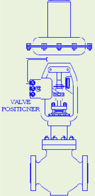
The MICROSET PNEUMATIC VALVE POSITIONER is an instrument working on force balance
principle to position the Control Valve stem in accordance to a pneumatic signal received from a
controller or manual loading station, regardless of packing box friction, actuator hysteresis or
unbalanced forces on the valve plug. Thus, the positioner ensures a reliable and accurate operation
of Control Valve.
APPLICATION:
NON-STANDARD CONTROLLER OUTPUT :The positioner is used to operate a valve with
3-15 psi spring range when controller signal is other than 3 –15 psi
NON-STANDARD ACTUATOR SPRING RANGE :The positioner is used to operate valves
Having non standard actuator spring ranges by controllers having the standard 3-15 psi
Signal pressure.
REMOTE VALVE LOCATION :When air operated control valves are located far from control
Instrument, positioner will reduce lag, thereby speeding up valve operation.
SPLIT RANGE :Some processes require the dual or sequential operation of two to three
Control valves by a single controller with a 3-15 psi output signal range.
IMPROVES OVER ALL PERFORMANCE :When process lags necessitate the use of wide
Controller proportional band, the positioner provides an exact means of making the control
Valve responsive to infinitely small changes in controller output pressure.
TECHNICAL SPECIFICATION :
MODEL
: MIC-VP-1 Single Acting - Direct Action.
: MIC- VP-2 Single Acting - Reverse Action.
: MIC-VP-3 Double Acting - Direct Action.
SUPPLY CONNECTION
: 1 /4” NPT (F)
SUPPLY AIR PRESSURE
: 1.4 to 3.5 kg/cm² (Standard.)
: 5.0 kg/cm² (Maximum)
INPUT
: 0.2 – 1.0 kg/cm² (Standard)
: 0.2 – 0.6 kg/cm² (Split Range)
: 0.6 – 1.0 kg/cm² (Split Range)
HYSTERESIS
: Within ± 1% of FS.
LINEARITY
: Within ± 1% of FS.
DEAD BAND
: Within 0.1% of FS.
STROKE SPEED (Max)
: 10mm/sec
STROKE
: 14 mm to 100mm
AIR CONSUMPTION
: 7.0 NL / Min (Normal.)
AIR FLOW CAPACITY
: 200 NL / Min (Maximum.)
MATERIAL OF CONSTRUCTION
HOUSING
: Die cast aluminum to LM – 6.
INTERNALS & LINKAGE
: AISI 304
DIAPHRAGM
: Nitrile / Neoprene with nylon fabric reinforcement.
DESIGN AND PERFORMANCE FEATURES :
High sensitivity and stability.
Simple zero and span adjustments.
Field reversibility.
Large port pilot relay eliminates the air passage blockage.
Internal components are of stainless steel.
PRINCIPLE OF OPERATION:
PNEUMATIC VALVE POSITIONER is force balance device which, ensure the position of the plug,
which is directly proportional to the controller output pressure. The Positioner compares the forces
generated by the control signal and the control valve stem through the motion connector and the
feedback cam, and accordingly it feeds or bleeds the air going to the valve actuator.
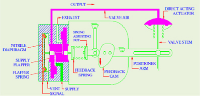
The instrument air signal is applied to the signal diaphragm. An increase in signal will drive the
diaphragm and flapper-connecting stem to the right. The flapper-connecting stem will then open
the supply flapper admitting supply pressure into the output which is connected to the actuator
diaphragm. The exhaust flapper remains closed when the flapper connecting stem is deflected to
right. The effect of increasing signal is to increase the pressure in the actuator. This increased
pressure in the actuator drives the valve stem downward and rotates the positioner lever
clockwise. This clockwise rotation of the lever results in a compression of range spring through
cam. When the valve stem reaches the position called for by the controller, the compression in the
range spring will give a balance force resulting the closure of both the flapper.
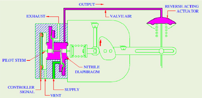
If the control signal is decreased, the force exerted by the signal diaphragm will also decrease and
the force from the range spring will push the flapper-connecting stem to the left, opening the
exhaust flapper. This causes a decrease actuator diaphragm pressure and allows the valve stem to
move upward until a new force balance is established.
SCHEMATIC DIAGRAM (DIRECT ACTING)
SCHEMATIC DIAGRAM (REVERSE ACTING)
The company’s policy is one of the continuous product improvements and the right is reserved to
modify the specifications contained herein without notice.


 1
1 2
2 3
3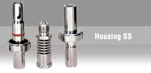 4
4 5
5 6
6 7
7 8
8 9
9 10
10 11
11 12
12 13
13 14
14 15
15 16
16 17
17 18
18 19
19 20
20 20
20