 |
| DIAPHRAGM CONTROL VALVE |
INTRODUCTION
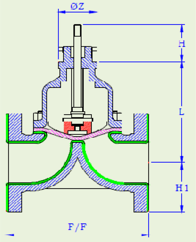
The Diaphragm Valve is essentially a simple pinch clamp, closed by pressing a flexible diaphragm against transverse weir, when fully closed, the diaphragm seats against the weir providing a leak tight closure. The diaphragm valves are recommended for handling sticky and viscous fluids, slurries and highly corrosive and hazardous substances and other hard to handle mediums or where tight closure is prime factor. It is the most ideal valve to handle fluids that require high purity and should remain free from contamination. The Diaphragm Valve is a simple pinch type valve and of low pressure type because of large area of diaphragm and is extensively used for both
On/Off and throttling services and finds its application in Waste & Water Treatment Plants, Filtration Plants, Chlorination Plants etc. |
|
| SPECIFICATION : |
DESIGN |
Confirm to BS - 5156 |
| BODY TYPE |
Weir (Rubber Lined – Series MIC 521)
(Unlined – Series MIC 541)
(PFA Lined – Series MIC 551) |
| VALVE SIZE |
15mm to 300mm (1/ 2" to 12") |
| END CONNECTION |
ANSI B 16.1Class 150 |
| BODY MATERIAL |
Cast Iron (IS 210 grade FG 200)
Cast Steel, Other alloys on request. |
| LINING MATERIAL |
Ebonite, PVDF, PFA, PP, EPDM, Glass etc. |
| LINING HARDNESS |
Ebonite-95° ± 5 Shore A
Natural/Neo Rubber-55° ± 5 Shore A
Teflon-Rockwell/Shore R100 D78 or
D62 Glass lining & FRP-Parcol Parcol 40
Respectively. |
| LINING THICKNESS |
15 to 65 mm Valve - 3.0 mm
80 to 100 mm Valve - 3.5 mm
125 to 150 mm Valve - 4.0 mm
200 to 300 mm Valve - 5.0 mm
Teflon Coating Thickness – 800 micron,
Glass Lining – 1.5mm. |
| BODY DIAPHRAGM |
Neoprene, Teflon Backed with Neoprene
Butyl, Viton, Hyplon, Nitrile, EPDM. |
| LEAKAGE RATE |
As per ANSI B 16.104 Class VI (100% Leak tight.) |
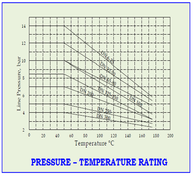
| TEMPERATURE |
- 30°C to 80°C |
| FLOW CHARACTERISTICS |
BS 6755 Part - I |
| TESTING STANDARD |
May be adjusted throughout a spring range
by turning the adjusting screw. |
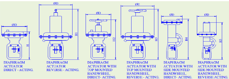
| ACTUATOR TYPE |
Diaphragm or Motorized or Cylinder |
| ACTUATOR ACTION |
Direct Acting - Normally Open (Air to Close)
Reverse Acting - Normally Close (Air to Open) |
| SPRING RANGE |
3 – 15 PSIG (0.2 – 1.0 Kg/cm2)
8 – 20 PSIG (0.4 – 2.0 Kg/cm2)
18 – 30 PSIG (1.2 – 2.0 Kg/cm2) |
| AIR SUPPLY |
20-50 PSIG (1.4-3.5 Kg/cm2) |
| AIR CONNECTION |
1/ 4" or 1/ 2" NPT |
| ACCESSORIES OPTIONAL |
Top or Side Mounted Handwheel, Limit Switches
Airset, Valve Positioner etc. |
|
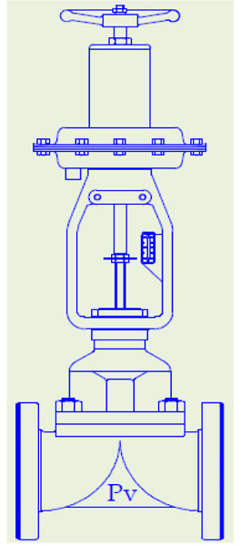
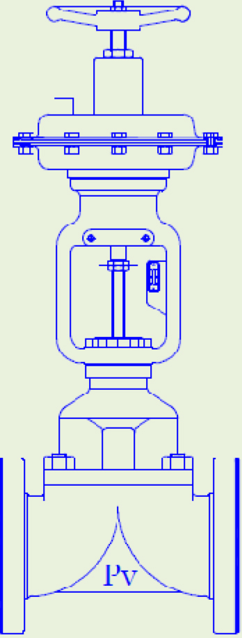
| DIAPHRAGM VALVE WITH REVERSE ACTUATOR |
DIAPHRAGM VALVE WITH DIRECT ACTUATOR |
 |
 |
|
| |
DESIGN AND PERFORMANCE FEATURES :
- It is a full bore straight through, give high flow performance with minimum turbulence,
while giving 100% leak tight closure.
- Perfect sealing and longer diaphragm life due to weir design.
- Valve is self cleaning with no pockets, recesses, corners, grooves or sharp edges in the
direction of flow.
|
| |
VALVE SIZING CO-EFFICIENT Cv RATINGS
VALVE SIZE |
TRAVEL(in) |
RUBBER LINED |
UNLINED OR GLASS LINED |
(in) |
RUBBER |
TEFLON |
RUBBER |
TEFLON |
RUBBER |
TEFLON |
|
|
DIAPHRAGM |
DIAPHRAGM |
DIAPHRAGM |
DIAPHRAGM |
DIAPHRAGM |
DIAPHRAGM |
½ |
¼ |
¼ |
6 |
4 |
6 |
4 |
¾ |
3/8 |
3/8 |
12 |
6 |
9 |
6 |
1 |
3/8 |
9/16 |
15 |
12 |
12 |
10 |
1 ½ |
¾ |
¾ |
40 |
25 |
30 |
20 |
2 |
1 1/8 |
¾ |
55 |
35 |
50 |
30 |
2 ½ |
1 ¼ |
15/16 |
85 |
55 |
75 |
50 |
3 |
1 ½ |
1 ¼ |
120 |
75 |
95 |
70 |
4 |
1 ¾ |
1 ½ |
210 |
180 |
200 |
160 |
6 |
2 ¾ |
-- |
375 |
275 |
350 |
270 |
8 |
3 |
-- |
650 |
475 |
625 |
450 |
10 |
3 ½ |
-- |
870 |
1045 |
845 |
1020 |
12 |
4 |
-- |
1328 |
1503 |
1303 |
1478 |
|
| |
|
| |
| ACTUATOR SELECTION GUIDE FOR RUBBER LINED DIAPHRAGM VALVE |
| |
Valve Characteristics/Action |
On/Off/
Control Duty
Air to Open |
On/ Off
Air to Close |
Control Duty
Air to Close |
Air Supply to Actuator (Psig) |
25 |
35 |
18 |
28 |
38 |
28 |
28 |
Spring Range (Psig) |
8-20 |
18-30 |
3-6 |
3-15 |
Valve
Size |
Max.
Travel |
Actuator Size |
Shut Off Pressure
Kg/ Cm2 |
Shut Off Pressure
Kg/ Cm2 |
Shut Off Pressure
Kg/ Cm2 |
Upto 1” |
9/16” |
12 |
-- |
6.0 |
-- |
6.0 |
12.0 |
-- |
6.0 |
|
|
30 |
10.0 |
22.0 |
7.0 |
22.0 |
38.0 |
7.0 |
22.0 |
1 ½” |
¾” |
30 |
-- |
8.0 |
-- |
8.0 |
15.0 |
-- |
8.0 |
|
|
55 |
5.5 |
18.0 |
5.5 |
18.0 |
32.0 |
5.5 |
18.0 |
2” |
1 1/8” |
55 |
-- |
8.0 |
-- |
8.0 |
17.0 |
-- |
8.0 |
|
|
95 |
5.0 |
18.0 |
5.0 |
18.0 |
33.0 |
5.0 |
18.0 |
2 ½” |
1 ¼” |
55 |
-- |
7.5 |
-- |
7.5 |
14.0 |
-- |
7.5 |
|
|
95 |
4.0 |
16.0 |
4.0 |
16.0 |
28.0 |
4.0 |
16.0 |
3” |
1 ½” |
95 |
-- |
7.5 |
-- |
7.5 |
15.0 |
-- |
7.5 |
|
|
140 |
3.5 |
13.5 |
3.5 |
13.5 |
24.0 |
3.5 |
13.5 |
4” |
1 ¾” |
95 |
-- |
4.0 |
-- |
4.0 |
8.0 |
-- |
4.0 |
|
|
140 |
-- |
7.0 |
-- |
7.0 |
14.0 |
-- |
7.0 |
|
|
300 |
7.0 |
20.0 |
7.0 |
20.0 |
35.0 |
7.0 |
20.0 |
5” |
2” |
140 |
-- |
7.0 |
-- |
7.0 |
14.0 |
-- |
7.0 |
|
|
300 |
7.0 |
20.0 |
7.0 |
20.0 |
35.0 |
7.0 |
20.0 |
6” |
2 ¾” |
140 |
-- |
2.0 |
-- |
2.0 |
5.0 |
-- |
2.0 |
|
|
300 |
1.5 |
8.0 |
1.5 |
8.0 |
16.0 |
1.5 |
8.0 |
8” |
3” |
300 |
-- |
3.0 |
-- |
3.0 |
6.0 |
-- |
3.0 |
|
|
600 |
2.5 |
9.0 |
2.5 |
9.0 |
16.0 |
2.5 |
9.0 |
10” |
3 ½” |
600 |
0.5 |
5.7 |
0.5 |
5.7 |
11.0 |
0.5 |
5.7 |
12” |
4” |
600 |
0.4 |
3.0 |
0.4 |
3.0 |
6.0 |
0.4 |
3.0 |
|
| |
| |
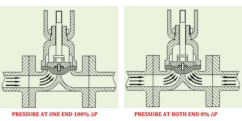
| LINE PRESSURE AT ONE END ONLY (FOR LINE PRESSURE AT BOTH ENDS MULTIPLY DP VALUES BY 0.5) |
| |
 |
| |
| ACTUATOR SELECTION GUIDE FOR PTFELINED DIAPHRAGM VALVE |
Valve Characteristics/Action |
On/Off/
Control Duty
Air to Open |
On/ Off
Air to Close |
Control Duty
Air to Close |
Air Supply to Actuator (Psig) |
25 |
35 |
20 |
35 |
30 |
40 |
Spring Range (Psig) |
8-20 |
18-30 |
3-6 |
3-15 |
Valve
Size |
Max.
Travel |
Actuator Size |
Shut Off Pressure
Kg/ Cm2 |
Shut Off Pressure
Kg/ Cm2 |
Shut Off Pressure
Kg/ Cm2 |
½” |
¼” |
30 |
6.0 |
12.0 |
9.5 |
15.5 |
9.5 |
15.5 |
|
|
55 |
10.0 |
NA |
15.5 |
NA |
15.5 |
NA |
¾” |
3/8” |
30 |
7.0 |
12.0 |
9.5 |
15.5 |
9.5 |
15.5 |
|
|
55 |
10.0 |
NA |
15.5 |
NA |
15.5 |
NA |
1” |
9/16” |
30 |
3.5 |
7.5 |
2.5 |
11.5 |
2.5 |
11.5 |
|
|
55 |
7.5 |
13.5 |
14.0 |
NA |
14.0 |
NA |
1 ¼” |
9/16” |
30 |
NA |
4.0 |
2.5 |
7.5 |
2.5 |
7.5 |
|
|
55 |
5.0 |
13.5 |
9.5 |
NA |
9.5 |
NA |
1 ½” |
¾” |
30 |
NA |
3.5 |
1.0 |
4.5 |
1.0 |
4.5 |
|
|
55 |
5.0 |
13.5 |
5.5 |
15.5 |
5.5 |
15.5 |
2” |
¾” |
55 |
2.0 |
9.0 |
5.5 |
15.5 |
5.5 |
15.5 |
|
|
95 |
4.5 |
13.5 |
7.5 |
NA |
7.5 |
NA |
|
|
140 |
12.0 |
NA |
NA |
NA |
NA |
NA |
2 ½” |
15/16” |
55 |
1.0 |
6.0 |
2.0 |
15.5 |
2.0 |
15.5 |
|
|
95 |
3.0 |
10.5 |
5.5 |
15.5 |
5.5 |
15.5 |
|
|
140 |
9.0 |
NA |
15.5 |
NA |
15.5 |
NA |
3” |
11/4” |
55 |
NA |
4.0 |
1.0 |
6.5 |
1.0 |
6.5 |
|
|
95 |
4.0 |
12.0 |
8.0 |
15.5 |
8.0 |
15.5 |
4” |
11/2” |
140 |
2.0 |
6.5 |
3.5 |
11.0 |
3.5 |
11.0 |
|
|
300 |
4.0 |
13.5 |
8.5 |
NA |
8.5 |
NA |
6” |
2” |
300 |
2.0 |
7.0 |
4.5 |
11.0 |
4.5 |
11.0 |
8” |
2 ¼” |
300 |
NA |
3.0 |
1.0 |
3.5 |
1.0 |
3.5 |
|
| |
| LINE PRESSURE AT ONE END ONLY |
| |
| (FOR LINE PRESSURE FROM BOTH SIDES MULTIPLY DP VALUES BY 0.5) ACTUATOR |
| |
LINE PRESSURE AT ONE END ONLY
(FOR LINE PRESSURE FROM BOTH SIDES MULTIPLY DP VALUES BY 0.5) ACTUATOR
|
| |
| ACTUATOR DIMENSIONS |
| |
 |
| |
| |
ACTUATOR
MODEL |
EFFECTIVE
Inch2 |
BONNET
MOUNT
DIA. |
TRAVEL |
ФD |
H |
H1 |
H2 |
H3 |
H4 |
H5 |
MIC-R 123 |
12 |
32 |
14.3 |
150 |
- |
370 |
- |
365 |
- |
- |
MIC-D 123 |
12 |
32 |
14.3 |
150 |
235 |
- |
335 |
- |
- |
- |
MIC-R 141 |
30 |
32 |
19 |
218 |
- |
440 |
- |
400 |
- |
- |
MIC-D 141 |
30 |
32 |
19 |
218 |
295 |
- |
390 |
- |
- |
- |
MIC-R 141 |
30 |
54 |
32 |
218 |
- |
510 |
- |
520 |
- |
- |
MIC-D 141 |
30 |
54 |
32 |
218 |
325 |
- |
475 |
- |
- |
- |
MIC-R 166 |
55 |
54 |
28 |
286 |
- |
550 |
- |
570 |
- |
640 |
MIC-D 166 |
55 |
54 |
28 |
286 |
410 |
- |
540 |
- |
640 |
- |
MIC-R 166 |
55 |
54 |
38 |
286 |
- |
570 |
- |
590 |
- |
690 |
MIC-D 166 |
55 |
54 |
38 |
286 |
325 |
- |
510 |
- |
690 |
- |
MIC-R 106 |
95 |
54 |
32 |
371 |
- |
680 |
- |
700 |
- |
670 |
MIC-D 106 |
95 |
54 |
32 |
371 |
430 |
- |
770 |
- |
670 |
- |
MIC-R 106 |
95 |
54 |
45 |
371 |
- |
700 |
- |
720 |
- |
725 |
MIC-D 106 |
95 |
54 |
45 |
371 |
590 |
- |
550 |
- |
725 |
- |
MIC-R 251 |
140 |
54 |
38 |
443 |
- |
840 |
- |
640 |
- |
860 |
MIC-D 251 |
140 |
54 |
38 |
443 |
750 |
- |
1000 |
- |
860 |
- |
MIC-R 251 |
140 |
90.5 |
70 |
443 |
- |
870 |
- |
890 |
- |
1000 |
MIC-D 251 |
140 |
90.5 |
70 |
443 |
750 |
- |
1000 |
- |
1000 |
- |
MIC-R 411 |
300 |
90.5 |
45 |
599 |
- |
980 |
- |
- |
- |
1230 |
MIC-D 411 |
300 |
90.5 |
45 |
599 |
950 |
- |
- |
- |
1230 |
- |
MIC-R 411 |
300 |
90.5 |
70/76 |
599 |
- |
1070 |
- |
- |
- |
1275 |
MIC-D 411 |
300 |
90.5 |
70/76 |
599 |
950 |
- |
- |
- |
1275 |
- |
- Operates automatically off line pressure.
- Heavy-duty, nylon-reinforced diaphragm.
- Round-shaped, soft seat seal provides drip-tight class VI closure.
- Diaphragm assembly guided top and bottom.
|
| BODY DIMENSIONS |
SIZE |
F/F |
H1 |
L |
H |
ØZ |
Approx
Weights, In
Kgs. |
Inch |
mm |
Lined |
Unlined |
|
|
|
|
|
½ |
15 |
114 |
108 |
45 |
75 |
117 |
31.7 |
2.50 |
¾ |
20 |
123 |
117 |
50 |
85 |
117 |
31.7 |
2.75 |
1 |
25 |
133 |
127 |
55 |
97 |
117 |
31.7 |
3.50 |
1 ¼ |
32 |
152 |
146 |
60 |
90 |
117 |
31.7 |
5.50 |
1 ½ |
40 |
162 |
159 |
70 |
110 |
117 |
31.7 |
6.75 |
2 |
50 |
196 |
190 |
75 |
135 |
117 |
53.9 |
11 |
2 ½ |
65 |
222 |
216 |
90 |
155 |
143 |
53.9 |
16.65 |
3 |
80 |
261 |
254 |
95 |
175 |
143 |
53.9 |
22.9 |
4 |
100 |
312 |
305 |
115 |
200 |
143 |
53.9 |
34.8 |
5 |
125 |
364 |
350 |
125 |
230 |
143 |
53.9 |
46.5 |
6 |
150 |
414 |
406 |
140 |
360 |
197 |
69.8 |
75 |
8 |
200 |
531 |
521 |
175 |
370 |
197 |
69.8 |
156 |
10 |
250 |
645 |
635 |
204 |
559 |
229 |
69.8 |
230 |
12 |
300 |
759 |
749 |
242 |
651 |
229 |
69.8 |
399 |
|
 |
| |
INSTALLATION
The valve should be installed preferably in a straight run of the pipe, a few diameters away from the bends. The preferred position is with actuator vertically above or below the valve body. It may also be installed in a horizontal or angled position provided the diaphragm actuator is supported. Necessary clearance should be provided above the actuator to permit removal for servicing or for inspection of the valve internals. The supply pressure to the actuator be either 20 psig or 35 psig or as per rating indicated on the name plate. For control applications, positioner mounted are piped and adjusted at the factory. |
| |
| |
FINAL CHECK
After the valve has been installed, check the operations for full stroke travel as indicated on the name plate. Check for air leaks in air line connection. Open and close the valve two or three times to ensure proper operation. Before commissioning the process flow, it would be advisable to use conical filter or other temporary devices to avoid damage to the rubber lining or body diaphragm as the fluid is likely to carry foreign solid material during testing or commissioning of the plant. This care is particularly important with neoprene or other soft elastomer lining. Special care has to be exercised with glass lining construction. It is generally not desirable to use excessive air pressure to the actuator than specified as it would reduce the life of the body diaphragm and also cause undue forces on the actuator diaphragm. Valves having manual hand wheels should be preferably operated with air pressure, particularly during the start of the plant when any foreign material is
likely to damage the internals. |
| |
| |
All type of regulators generally fit into one of the following two basic categories.
1) Direct Operated
2) Pilot Operated
The specific considerations peculiar to your control needs is to be carefully studied and understood
to determine which method of control is the better choice. Regulators when compared to control
Valve / Instrument package have their advantages and limitations.
Table No.2 lists selected characteristic of both. |
| |
| The Company’s policy is one of continuous product improvement and the right is reserved to modify the specifications contained herein without notice. |
| |


 1
1 2
2 3
3 4
4 5
5 6
6 7
7 8
8 9
9 10
10 11
11 12
12 13
13 14
14 15
15 16
16 17
17 18
18 19
19 20
20 20
20