 |
GLOBE 3 WAY CONTROL VALVE MIC – 241
INTRODUCTION
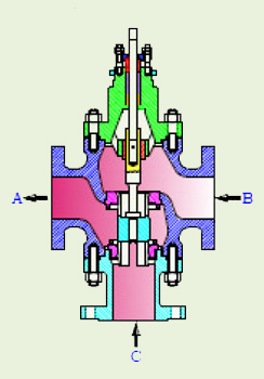
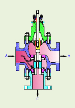
MSSet 3 way control valves are used to combine two flows or to divert one flow into two outlets. They are designed to replace and perform the functions of two single ported control valves acting in opposite directions, in converging or diverging liquid flow. They can be used to control the circulation of water, oil, sea water or other liquid in heating or cooling applications involving heat exchanger bypass control.They can also be used in blending systems and on-off selector systems.
|
|
| SPECIFICATION : |
DESIGN |
ASME B16.34 |
| BODY DESIGN |
Globe type with Tail piece to provide third port. |
| VALVE SIZE |
15 to 300 mm(1/2" to 12") |
| RATING |
ANSI 150 to 600 Equivalents to BS, DIN, IS, JIS, etc. |
| END CONNECTION |
Flanged–15mm to 300mm (1/2" to 12") |
| BODY MATERIALS |
Carbon Steel, Chrome-moly Steel, Stainless Steel, Monel, Alloy20, Hastelloy
B/C, Duplex Stainless Steel, Aluminum Bronze etc.
|
| BONNET |
Standard upto 250°C
: Normalizing (Finned) between 250°C to 500°C
: Extended cold service - 20°C to - 100°C
: Cryogenic - 100°C to - 250°C
: Bellows seals. |
| GLAND PACKING |
Grafoil / PTFE V Rings, Low Emission |
| TRIM DESIGNS |
Skirt Guided. Linear, Pressure Balance. |
| TRIM MATERIALS |
Stainless Steel, Alloy20, Monel, Duplex Stainless Steel, 13%
Chrome Steel Hastelloy B/C, Stellite (Alloy 6) |
| CHARACTERISTICS |
Linear, On / Off. |
| SEAT LEAKAGE |
As per FCI-70-2 (ANSI B 16.104)
Class IV, V and VI (STANDARD LEAKAGE RATES)
Metal to Soft Seating–
Bubble tight (Zero Leakage)
|
| ACTUATOR TYPE |
Diaphragm, Piston or Electric. |
| ACTUATOR ACTION |
Direct / Reverse Acting.Direct acting air failure "Close" Top Port. |
| DIAPHRAGM |
Nitrile / Neoprene.(Nylon reinforced) |
| SPRING RANGES |
3–15 PSIG (0.2–1.0 Kg/cm2)
: 6 -30 PSIG (0.4-2.0 Kg/cm2) |
| AIR SUPPLY |
20–35 PSIG (1.4–2.5 Kg/cm2) |
| AIR CONNECTION |
1/ 4”or 1/ 2” NPT |
| ACCESSORIES |
Valve Positioner - Pneumatic, Electro Pneumatic, Smart Positioner.
|
|
|
|
| |
Instruments :
Airset, Solenoid Valve, Air Lock, Volume Booster, Position Transmitter, Limit– Proximity Switches etc.
FEATURES :
Top or Side Mounted hand wheel, Limit Stops Removable Blind Head, Steam Jacketing, etc.
|
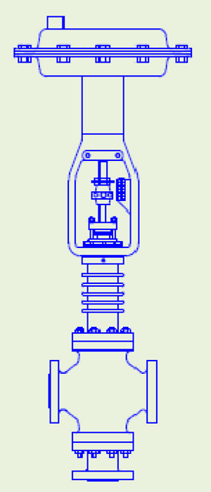
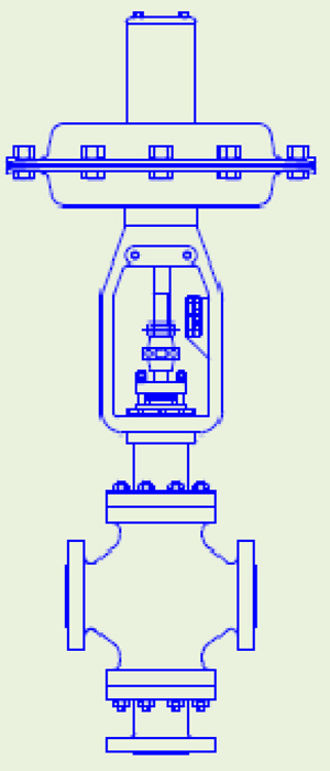
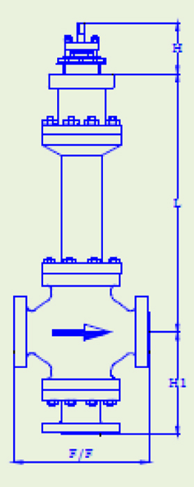
| CONTROL VALVE WITH FINNED BONNET AND DIRECT ACTUATOR |
CONTROL VALVE WITH STANDARD BONNET |
 |
 |
|

|
|
DESIGN FEATURES
-
High flow Valve capacity and range ability.
-
Heavy - Duty stem.
-
Wide range of interchangeable trim sizes.
-
Bellow seals available for positive stem sealing.
-
Comprehensively designed and tested to ensure its optimum performance for the tough process parameters specified.
-
Wide selection of actuator.
QUALITY AND PERFORMANCE GUARANTEE :
-
Produced with Quality Systems accredited to ISO 9001:2008
-
CE ”in accordance with Pressure Equipments Directive and Regulations By Lloyd’s Register.
-
Full material certification available for all major component Parts.
-
Full guarantee on design and Performance.
-
All testing performed to the requirements of ANSI B16.34.
|
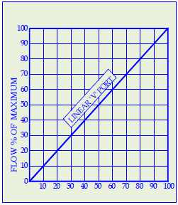
CHARACTERISTIC CURVE
The inherent flow characteristic of a Control valve is the relationship between the flow and the lift of the plug at a constant Pressure drop.
|
|
|
|
|
RANGE ABILITY
The Inherent range ability of MSSet standard trims is as given under.
| TRIM SIZE |
Inch |
mm |
Rangeability |
| 1/4 to 3/4 |
6 to 20 |
35:1 |
| 1 to 3 |
25 to 80 |
50:1 |
| 4 to 12 |
100 to 300 |
60:1 |
|
|
MAXIMUM RECOMMENDED VALVE BODY VELOCITY FOR LIQUID FLOWS
| Trim style |
Valve Size |
Valve body material |
| Carbon Steel |
Alloy Steel |
Aluminium Bronze |
| Inch |
mm |
m/s |
m/s |
m/s |
| Linear |
1 to 2 |
25 to 50 |
10.5 |
12.0 |
7.0 |
| 3 to 8 |
80 to 200 |
9.0 |
10.0 |
6.5 |
| 10 to 12 |
250 to 300 |
6.0 |
8.0 |
5.5 |
|
|
MAXIMUM RECOMMENDED VALVE BODY VELOCITY FOR GAS/VAPOUR FLOWS
| Valve Size |
Maximum |
Maximum |
Maximum outlet mach No.
for predicted noise level |
| Inlet velocity |
Outlet velocity |
| Inch |
mm |
m/s |
m/s |
>95dBA |
<95dBA |
<85dBA |
| ½ to 2 |
15 to 50 |
80 |
200 |
0.65 |
0.5 |
0.3 |
| 3 and 4 |
80 and 100 |
75 |
200 |
0.65 |
0.5 |
0.3 |
| 6 and 8 |
150 and 200 |
65 |
200 |
0.65 |
0.5 |
0.3 |
| 10 and 12 |
250 and 350 |
55 |
200 |
0.65 |
0.5 |
0.3 |
|
VALVE SIZING CO-EFFICIENT Cv RATING:
Valve Size |
Trim Size |
CV Value |
Inch |
mm |
Inch |
|
½ |
15 |
½ |
5 |
3/8 |
3.2 |
¼ |
2 |
¾ |
20 |
¾ |
8 |
½ |
5 |
3/8 |
3.2 |
¼ |
2 |
1 |
25 |
1 |
11 |
¾ |
8 |
½ |
5 |
3/8 |
3.2 |
¼ |
2 |
1 ½ |
40 |
1 ½ |
28 |
1 ¼ |
17 |
2 |
50 |
2 |
42 |
1 ½ |
28 |
3 |
80 |
3 |
105 |
2 ½ |
70 |
4 |
100 |
4 |
185 |
3 |
105 |
6 |
150 |
6 |
405 |
5 |
275 |
8 |
200 |
8 |
605 |
6 |
405 |
10 |
250 |
10 |
880 |
8 |
605 |
12 |
300 |
12 |
1265 |
10 |
880 |
|
Configuration- Standard Range |
|
|
 |
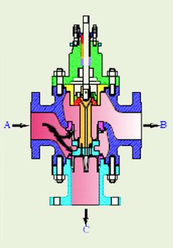 |
| Valve for Mixing Service |
Valve for Diverting Service |
Valve with PressureBalance Trim |
|
| |
|
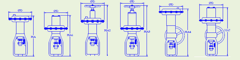
ACTUATOR DIMENSION
|
ACTUATOR
MODEL |
EFFECTIVE
Inch2 |
BONNET
MOUNT
DIA. |
TRAVEL |
ФD |
HA |
HA1 |
HA2 |
HA3 |
HA4 |
HA5 |
MIC-R 141 |
30 |
54 |
28 |
218 |
- |
356 |
- |
494 |
- |
650 |
MIC-D 141 |
30 |
54 |
28 |
218 |
372 |
- |
529 |
- |
650 |
- |
MIC-R 166 |
55 |
54 |
28 |
286 |
- |
494 |
- |
566 |
- |
697 |
MIC-D 166 |
55 |
54 |
28 |
286 |
471 |
- |
678 |
- |
673 |
- |
MIC-R 166 |
55 |
71.5 |
38 |
286 |
- |
542 |
- |
615 |
- |
746 |
MIC-D 166 |
55 |
71.5 |
38 |
286 |
520 |
- |
727 |
- |
722 |
- |
MIC-R 106 |
95 |
54 |
28 |
371 |
- |
513 |
- |
588 |
- |
730 |
MIC-D 106 |
95 |
54 |
28 |
371 |
505 |
- |
711 |
- |
707 |
- |
MIC-R 106 |
95 |
71.5 |
38 |
371 |
- |
577 |
- |
651 |
- |
779 |
MIC-D 106 |
95 |
71.5 |
38 |
371 |
555 |
- |
760 |
- |
756 |
- |
MIC-R 251 |
140 |
71.5 |
38 |
443 |
- |
601 |
- |
681 |
- |
848 |
MIC-D 251 |
140 |
71.5 |
38 |
443 |
573 |
- |
852 |
- |
821 |
- |
MIC-R 251 |
140 |
90.5 |
57 |
443 |
- |
736 |
- |
816 |
- |
983 |
MIC-D 251 |
140 |
90.5 |
57 |
443 |
708 |
- |
988 |
- |
956 |
- |
MIC-R 411 |
300 |
71.5 |
38 |
616 |
- |
772 |
- |
- |
- |
1098 |
MIC-D 411 |
300 |
71.5 |
38 |
616 |
723 |
- |
- |
- |
1075 |
- |
MIC-R 411 |
300 |
90.5 |
57 |
616 |
- |
823 |
- |
- |
- |
1149 |
MIC-D 411 |
300 |
90.5 |
57 |
616 |
773 |
- |
- |
- |
1075 |
- |
MIC-R 411 |
300 |
90.5 |
90 |
616 |
- |
984 |
- |
- |
- |
1312 |
MIC-D 411 |
300 |
90.5 |
90 |
616 |
937 |
- |
- |
- |
1239 |
- |
MIC-R 411 |
300 |
90.5 |
102 |
616 |
- |
1030 |
- |
- |
- |
1426 |
MIC-D 411 |
300 |
90.5 |
102 |
616 |
1030 |
- |
- |
- |
1550 |
- |
|
- MIC- D : Direct Acting Actuator ( used on supply failure Valve – Opens Bottom Port)
- MIC- R : Reverse Acting Actuator ( used on supply failure Valve – Closes Bottom Port)
- All dimensions in mm.
|
| |
 |
 |
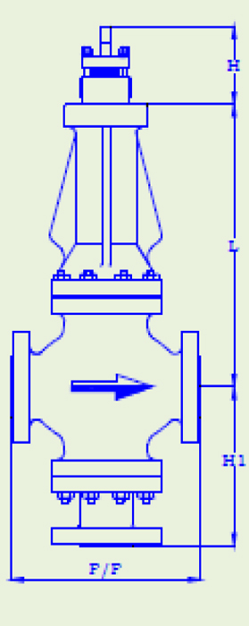 |
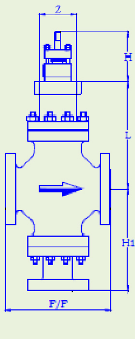
VALVE WITH STANDARD BONNET |
VALVE WITHNORMALIZING BONNET |
VALVE WITH BELLOW SEALBONNET |
|
|
| |
| Valve Size |
ANSI 150 (NP 10,16 BS-10-D,E) |
ANSI 300
(NP 25,40
BS-10-F,H,J) |
ANSI 600
(NP 64,100
BS-10-K,R) |
STEM IN
UP
POSITION |
BONNET
MOUNT
DIA |
HEIGHT FROM CENTER LINE |
CENTR
LINE TO
BASE |
STEM
TRAVEL |
| |
|
STANDARD |
NORMALIZING |
BELLOW |
| Inch |
mm |
FACE TO FACE (F/F) |
H |
Z |
L |
H1 |
28 |
| ½ |
15 |
184 |
190 |
203 |
117 |
53.97 |
140 |
192 |
324 |
156 |
28 |
| ¾ |
20 |
184 |
194 |
206 |
117 |
53.97 |
140 |
192 |
324 |
156 |
28 |
| 1 |
25 |
184 |
197 |
210 |
117 |
53.97 |
140 |
192 |
324 |
156 |
28 |
| 1 ½ |
40 |
223 |
235 |
251 |
117 |
53.97 |
159 |
245 |
353 |
160 |
28 |
| 2 |
50 |
254 |
267 |
286 |
117 |
53.97 |
168 |
248 |
362 |
178 |
28 |
| 2 ½ |
65 |
276 |
292 |
311 |
143 |
71.44 |
203 |
311 |
467 |
204 |
38 |
| 3 |
80 |
299 |
318 |
337 |
143 |
71.44 |
203 |
330 |
467 |
226 |
38 |
| 4 |
100 |
352 |
368 |
394 |
143 |
71.44 |
206 |
357 |
480 |
257 |
38 |
| 6 |
150 |
451 |
473 |
508 |
197 |
90.42 |
276 |
394 |
676 |
296 |
57 |
| 8 |
200 |
543 |
568 |
610 |
197 |
90.42 |
292 |
435 |
716 |
358 |
57 |
| 10 |
250 |
673 |
708 |
752 |
229 |
90.42 |
390 |
632 |
-- |
441 |
90 |
| 12 |
300 |
737 |
775 |
819 |
229 |
90.42 |
405 |
647 |
-- |
455 |
90 |
|
| |
The Company's policy is one of continuous product improvement and the right is reserved to modify the specifications contained herein without notice. |
| |
| |
|


 1
1 2
2 3
3 4
4 5
5 6
6 7
7 8
8 9
9 10
10 11
11 12
12 13
13 14
14 15
15 16
16 17
17 18
18 19
19 20
20 20
20