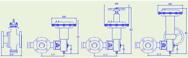
| SPECIFICATION : |
DESIGN |
BS. 5351 |
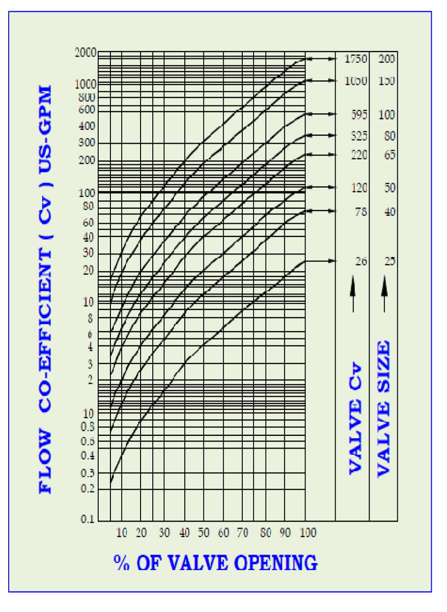
| SIZE |
25 to 200 mm (1" to 8") |
| RATING |
ANSI 150 |
| END CONNECTION |
Flanged End |
| F/F DIMENSIONS |
ANSI B-16.10 |
| FLOW CHARACTERISTICS |
Modified Equal Percentage,
Linear, On-Off. |
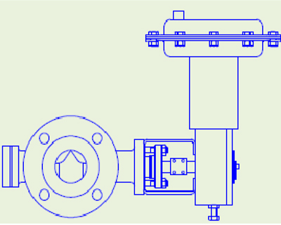
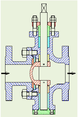
| FLOW DIRECTION |
Forward (into convex face of V-ball) |
| MAX. BALL ROTATION |
90˚ |
| BODY MATERIAL |
Carbon Steel, Stainless Steel, and Alloy
Steel etc. |
| BALL MATERIAL |
CF8M Chrome plated/Alloy steels. |
| SEAT RING |
PTFE, Carbon Filled Teflon. |
| BALL RING |
CF8M, Alloy steels |
| GASKET |
PTFE, Graphite Laminate. |
| GLAND PACKING |
PTFE V Rings, Grafoil. |
| ACTUATOR FORM |
Diaphragm, Rotary, Electric |
| ACTUATOR TYPE |
Scotch |
| DIAPHRAGM |
Nitrile / Neoprene |
| SPRING RANGE |
3 – 15 Psig (0.2 – 1.0 Kg/cm²) |
| 6 – 30 Psig (0.4 – 2.0 Kg/cm²) |
| AIR SUPPLY |
20 – 35 Psig (1.4 – 2.5 Kg/cm²) |
| AIR CONNECTION |
1/ 4" or 1/ 2" NPT |
| ACCESSORIES OPTIONAL |
Valve Positioner – Pneumatic,
Electro Pneumatic, Smart, Airset,
Solenoid Valve, Air Lock,
Volume Booste, Position Transmitter,
Limit Switches etc.
Top or Side Mounted Handwheel |
|


 1
1 2
2 3
3 4
4 5
5 6
6 7
7 8
8 9
9 10
10 11
11 12
12 13
13 14
14 15
15 16
16 17
17 18
18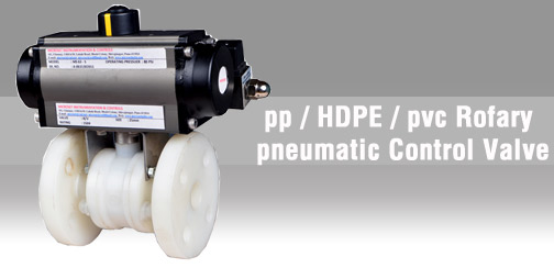 19
19 20
20 20
20